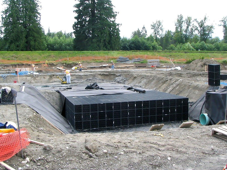
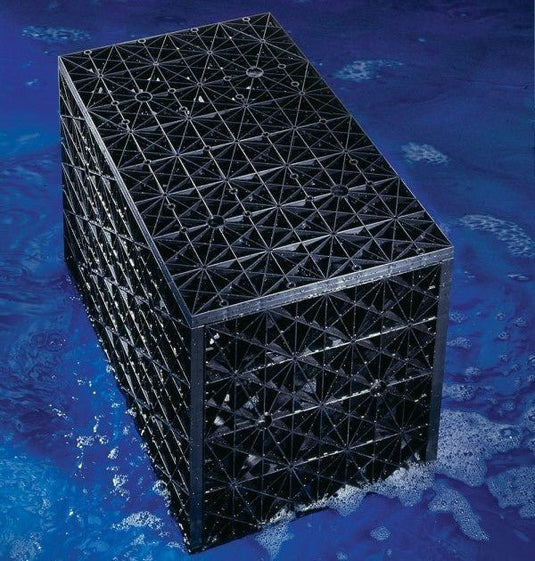
Whether you're a tradie looking to use the Atlantis underground infiltration system for your next project, or a homeowner who needs a versatile stormwater solution, Eco Sustainable House can help. We've compiled a basic guide below to give customers and installers alike an idea of how the system is put into the ground and assembled.
The photos shown here and the steps laid out are based on a typical infiltration tank for a residential project. Atlantis Flo Tanks can also be used for Detention and Rainwater Harvesting applications.
1. Assemble the tanks onsite
Once you've purchased your Atlantis Flo tank modules, they will arrive in flat packed bundles. This makes them easy to transport to where your tank is being installed, saving the need for cranes and other heavy machinery. Using a rubber mallet and a bit of manual labour, anyone can assemble the tanks.

Each tank only takes a few minutes to put together, as the video below demonstrates.
The simple pin-and-hole system allows you to customise the number of internal plates to suit the loading requirements. Plus, you can stack the modules vertically just by leaving out one of the large plates off each cube. This means you can create any shape for your infiltration system and minimise the lateral area needed to meet the water storage requirements.

2. Excavate the pit & lay geofabric
Excavation may be completed prior to the tanks arriving or being assembled, or the tanks might be ready to go in already. In either case the pit needs to be sufficient size to accommodate not only the modules themselves but the minimum top, side and base backfill.
Rainwater and On Site Detention tanks would also require an impermeable liner along the base and up the sides to be installed at this stage.
If possible, lay a base (100mm) of smooth, clean washed river sand, free from lumps or debris that may damage the geofabric or make the tank uneven. Keep an eye out for the presence of soft or muddy soils, as your system should be at least 1 metre above the ground water table.
3. Place Flo Tank Modules inside pit
Thanks to their light weight and modularity, the Atlantis Flo Tanks are much easier to install than the concrete equivalent. Each module can be moved by hand and placed side-by-side with the others to create any shape. This means you could have an L-shape or U-shape, or any other orientation you need to fit your site. If loading tanks stacked Triple or greater, we recommend using a hand trolley or lifting with two people.
The modules do not need to be connected or glue horizontally. Assuming they have been place correctly on a flat surface, there should be no gaps in between. Using string lines as a guide, and starting in one corner, is a good way to make sure the system is lined up correctly.
4. Cut holes for inspection ports & filtration system intake (if required)
Depending on the application for your tank, you will have additional pipes going in and out of the system. This may be a filtration unit, an overflow pipe, an inspection port and so on. The recycled plastic of the matrix units can be cut into without worry of affecting the structure of the area around it. A jigsaw or equivalent tool can create the required holes easily. For larger units you may even want to do this step before some of the modules are placed into the pit.
If you are using plastic liner and geofabric, these will likely need to be cut as well. Refer to your manufacturer's instructions for this. Alternatively, a specialist company may provide a liner that has be pre-cut to fit your tank.
5. Wrap all tank modules in geofabric/geotextile
Assuming the geofabric has been laid correctly in Step 2, workers on site should now be able to simply fold those layers over the top of the tank. Aim to have a minimum overlap of 300mm at the joins and seams, with duct tape or equivalent used to cover where they meet. Try to use as few separate pieces as possible by opting for wider width rolls of geofabric.
The result should be a neatly wrapped tank covered on all sides with the fabric. Sealing the system in this way prevents backfill materials from entering the system.

If you are using a plastic liner, follow this same method for that as well, though welded seams may be required for certain retention applications.
6. Backfill area with desired substrate
Starting with the sides of the tank, refill the pit with soil, sand or equivalent backill material. Only leave your inspection ports and the top of the filtration unit uncovered. Never use infill materials containing clay. Compact the side fill as it is laid, in 150mm lots. Use a mechanical compactor if possible as the vibration will help eliminate any minor gaps between the modules
Minimum backfill (above the tank) for pedestrian loading is 300mm, preferably of washed river sand compacted to 95% proctor density. This increases to 600mm for vehicle loading applications. There should also be some side backfill, maximum 500mm, before the excavation line. Base fill as discussed in step 2. Be careful when placing the first layer on the top of the newly place tank so as not to move the tanks or break the geofabric lining.
Consult with an engineer and advise ESH if you are creating a concrete slab above the infiltration system. This will ensure the right number of internal plates has been used to cope with the weight.

Erect erosion control devises or otherwise direct any stormwater runoff, debris, silts or clay away from the tank until it has been commissioned by the plumber. And there you have your Atlantis system ready to meet all your infiltration needs!
*Please note this is a general guideline only, refer to the Flo Tank Assembly Guide linked below for full specifications.
These tanks are not made to be used as septic tank distribution pits.
ESH provides support only, and does not take responsibility for commercial estimating or specifying.
Find out more:


